How TESS points on board
A technical literature review · 15 October 2026
TESS holds its science field by measuring guide-star positions in its own science cameras and feeding the resulting small attitude errors to the spacecraft attitude-control system, which commands reaction wheels. Ground software chooses the guide stars and reference positions. Onboard software measures their displacements, estimates a rotation, and closes the control loop. The same process does not freeze every source on its detector: differential velocity aberration, camera-dependent effects, changes in guiding configuration, and fast jitter leave distinct signatures in the science images.
This report separates documented design, preflight predictions, flight observations, and interpretation for image analysis. In particular, the 2018 design paper is not a report of measured mission-long flight performance. Later release notes show changes in both control software and guide-camera use.
Contents
- 1. The thesis and paper you remembered
- 2. The physical and computational control loop
- 3. How the reference guide stars are chosen
- 4. What the ADHU actually does to each star image
- 5. From guide-star offsets to an attitude quaternion
- 6. What is public about the spacecraft controller—and what is not
- 7. Predicted performance: accuracy, stability, and averaging
- 8. Velocity aberration: the loop follows apparent stars
- 9. What changed in flight
- 10. Why pointing creates photometric errors
- 11. Ground products are not the onboard control variables
- 12. Implications for SynDiff image modeling
- 13. Evidence limits and unresolved implementation details
- 14. Conclusion
1. The thesis and paper you remembered
The exact pair is:
- Tam Nguyen Thuc Nguyen (2018), Fine-pointing system development and photometric precision assessment for the transiting exoplanet survey satellite. MIT PhD in Space Systems, supervised by Kerri Cahoy, 162 numbered pages. MIT record and original PDF. The most useful sections are Chapter 2, guide-star selection; Chapter 3, centroiding and attitude estimation; Chapter 4, closed-loop control simulations and aberration; Chapter 5, photometric consequences.
- Tam Nguyen et al. (2018), Fine-pointing performance and corresponding photometric precision of the Transiting Exoplanet Survey Satellite. JATIS 4(4), 047001; published 4 September 2018. DOI, author-hosted PDF. This is the concise journal treatment of the same research program. It is explicitly concerned with predicted performance and proposes subsequent comparison with on-orbit data.
The thesis is valuable beyond the paper: it documents background-pixel geometry, ROI tradeoffs, optional guide-star ranking, coordinate-system corrections found during software testing, and the proprietary boundary of the spacecraft simulator. The paper provides the most compact published description of the fine-guidance algorithm and its validation.
Search scope and collection
I searched MIT DSpace and the author's publication list, followed the core paper's references, and consulted NASA/HEASARC, MAST, mission documentation, and relevant arXiv papers. The collection includes the two core works, mission/camera/orbit papers, a ground-pipeline paper, a photometric demonstration using flight quaternions, and selected operational release notes. It is a focused collection of the publicly located engineering literature, not a claim that every paper mentioning TESS pointing has been found. Most planet papers do not describe onboard control and were excluded unless they supply useful pointing evidence.
The source catalogue lists downloaded files, upstream links, and failed retrievals. All original PDFs remain in the local research library; public links lead to their original hosts. The original documents are not rehosted wholesale here. Every successful download has a SHA-256 checksum in the local manifest. No new flight-telemetry reduction or pipeline experiment was performed.
2. The physical and computational control loop
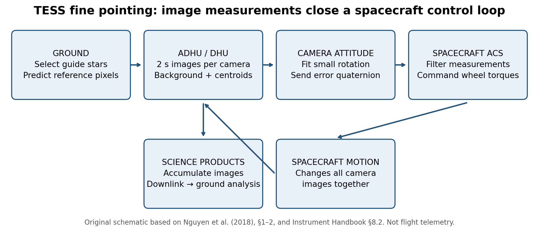
Figure 1. Original explanatory schematic, based on Nguyen et al. §1–2 and the Instrument Handbook §8.2. This is a functional diagram, not a timing-accurate simulation.
The important components are the four fixed science cameras; the instrument's Alternate Data Handling Unit (ADHU, also called DHU); the spacecraft Master Avionics Unit (MAU); and the body-mounted reaction wheels. The spacecraft also has dedicated star trackers and an inertial reference unit used outside nominal fine pointing. Fine pointing uses the instrument cameras themselves as the attitude sensors. The four cameras do not steer independently: wheel torques rotate the spacecraft carrying the entire camera assembly. Nguyen et al., §1.2 and Table 1.
A practical sequence is:
- Plan on the ground. Choose the desired sector/orbit attitude, identify suitable guide stars, and calculate their expected detector positions using the focal-plane geometry and apparent stellar positions.
- Upload tables and parameters. The MAU passes the guide-star tables and centroiding configuration to the ADHU.
- Slew and acquire in coarse pointing. The dedicated spacecraft sensors establish an attitude close enough that the expected guide stars are found in their image windows.
- Start camera data collection and fine pointing. The instrument measures guide-star centroids and computes a small error rotation for each camera.
- Filter and actuate. Camera error quaternions pass to the spacecraft ACS. The ACS estimates the appropriate correction and commands reaction-wheel torques.
- Repeat while collecting science data. The images used for guidance are the short integrations underlying longer accumulated science products. Ground photometry and WCS fitting occur later.
Which sensors are active?
| Mode in the 2018 design | Attitude sensing listed in Nguyen Table 1 | Actuator listed |
|---|---|---|
| Sun pointing | Coarse Sun sensors and inertial reference unit | Reaction wheels |
| DSN pointing | Star trackers and inertial reference unit | Reaction wheels |
| Coarse pointing | Star trackers and inertial reference unit | Reaction wheels |
| Fine pointing | Science cameras | Reaction wheels |
The Instrument Handbook §9.1.3 explicitly says that the star trackers are ignored in Fine Pointing mode. It would therefore be misleading to describe nominal fine pointing as a conventional gyro/star-tracker solution with science centroids merely added afterward. Thrusters have a separate operational role in momentum unloading; the table above is not an exhaustive description of propulsion operations. These statements describe the published architecture, not an audited list of sensors used by every subsequent flight-software version. Instrument Handbook.
Cadence: the frequently confused distinction
Each camera integrates for 2 seconds and supplies its own pointing estimate once per 2 seconds. The four camera readouts are staggered by 0.5 seconds, so with all cameras contributing, the MAU receives an updated estimate at 2 Hz, from a different camera on successive updates. This is not a 0.5-second exposure from every camera, and it is not a simultaneous four-camera attitude fit every 0.5 seconds. When a camera's guidance packet is invalid, its information is excluded. Nguyen et al., §1.2.
The 5 Hz time series in the paper's closed-loop experiments is the simulator's logging cadence. It is not the onboard image-guidance update rate. Similarly, a science product's coadd cadence is not the control-loop cadence.
3. How the reference guide stars are chosen
The published design uses approximately 200 guide stars per camera, across its focal plane, rather than 200 per CCD. They are selected on the ground, principally for useful brightness, clean surroundings, and reliable centroid measurement. The onboard loop operates on expected locations supplied in a table; it does not need to solve an unrestricted lost-in-space astrometric identification problem on each image. Nguyen et al., §2.
The preferred magnitude range is about 8–9, extendable to 9.5 when more stars are needed. Stars much brighter than this can saturate; fainter stars have poorer short-integration centroid precision. A narrow on-axis PSF can actually be disadvantageous because it is undersampled. Very broad corner PSFs may lose flux outside the centroid box. Consequently, minimum PSF width is not equivalent to optimum guide-star quality.
The paper's proximity filters are explicit:
| Contaminant or boundary | Published exclusion margin |
|---|---|
| Bright neighboring object, brighter than about magnitude 11 | 17 pixels radially |
| Variable neighboring star | 7 pixels radially |
| Saturated neighboring object | 15 pixels in row and a magnitude-dependent extra extent plus 15 pixels in column |
| CCD edge | 15 pixels in row and column |
| Detector straps | 15 pixels in row and column |
These are the 2018 selection recipe, not verified immutable parameters of today's guide tables. A variable neighbor matters because its changing contribution can move a flux-weighted centroid even if the spacecraft does not move. A nearby bright star can also become the brightest pixel in an acquisition window and be mistaken for the intended guide star. Nguyen et al., Table 2 and §2.2.
The thesis additionally investigates ranking candidates by modeled neighbor contamination and selecting a spatially distributed subset. Its pair-selection procedure retains the less contaminated star from close pairs, then removes high-contamination candidates from a buffered list. This is an optional improvement studied in the thesis, not evidence that the full ranking procedure necessarily runs in production. Basic parameter/proximity selection already met the tested requirements. Nguyen thesis, §2.3–2.5.
4. What the ADHU actually does to each star image
4.1 Acquisition window, background, and centroid window
The default guide-star postage stamp is 15 × 15 pixels. It contains a smaller, configurable centroiding region of interest (ROI). The thesis describes a default background-pixel ring with inner width 11 pixels and outer width 15 pixels; the median of the selected background pixels is subtracted before centroiding. Do not confuse the full acquisition stamp, the background ring, and the centroid ROI. Thesis, §3.2, pp. 74–77.
The published acquisition rule is deliberately simple:
- Find the brightest pixel in the postage stamp.
- If it lies outside the predefined centroid ROI, use the center of that brightest pixel as the star's position estimate.
- If it lies inside the ROI, use the background-subtracted first-moment centroid over that ROI.
The broad window allows recovery from coarse-pointing offsets. Outside the central ROI, a crude peak-pixel position can be safer than the centroid of a severely truncated PSF. Once the star is well centered, the flux-weighted centroid gives subpixel precision. This is not onboard PSF fitting or an ePSF optimization.
A standard mathematical expression for the documented centroid operation is
$$ \bar x=\frac{\sum_{p\in R}x_p(I_p-b)}{\sum_{p\in R}(I_p-b)},\qquad \bar y=\frac{\sum_{p\in R}y_p(I_p-b)}{\sum_{p\in R}(I_p-b)}. $$
Here $R$ is the configured centroid ROI; $p$ indexes its pixels; $x_p,y_p$ are pixel-center coordinates in pixels; $I_p$ is the measured pixel signal in a consistent detector-signal unit; $b$ is the measured median background in that same unit; and $\bar x,\bar y$ are the resulting centroid coordinates in pixels. This equation states the first-moment operation, not undocumented details of flight-code clipping or rejection.
The thesis's isolated-star tests favored a 7 × 7 ROI. Smaller windows truncate the PSF; larger ones add background noise. It also discusses 5 × 5 windows for crowded fields and uses them in acquisition tests. Neither value should be asserted as the universal flight configuration for all sectors. The actual ROI and background maps are configurable. Thesis, §3.2.2 and §3.4.
4.2 A subtle acquisition bias
A star can still have its brightest pixel inside the ROI while part of its PSF is outside it. Then the first moment is biased toward the reference window. The thesis demonstrates this as the star approaches the ROI edge. Once the peak exits the ROI, switching to its pixel center removes that truncation-driven bias, though the position estimate is coarser. This explains why acquisition accuracy is not simply the same small-jitter centroid precision extrapolated to large offsets.
The spiral tests were ground validation inputs, not a spacecraft search maneuver that TESS executes on every acquisition. They tested the flight-software response across the expected coarse-pointing offset range and exposed coordinate, indexing, background, and centroid-handling problems. Thesis, §3.4.
5. From guide-star offsets to an attitude quaternion
The ADHU combines many guide-star measurements into a small rotation of the camera, not an arbitrary shift for each star. The published method uses a small-angle model and a weighted least-squares objective. The journal paper gives the following component equations:
$$ x_i'=x_i+\phi y_i-\psi z_i,\qquad y_i'=y_i-\phi x_i+\theta z_i,\qquad z_i'=z_i+\psi x_i-\theta y_i. $$
Here $(x_i,y_i,z_i)$ is the dimensionless reference unit direction of guide star $i$ in the camera frame; $(x_i',y_i',z_i')$ is its modeled direction after the small rotation; and $\phi,\theta,\psi$ are fitted small angular parameters in radians, with the signs and ordering used in the source. These are unit-vector components, not raw CCD pixel coordinates. Nguyen et al., equations 1–3.
The objective is
$$ S(\theta,\phi,\psi)=\sum_{i=1}^{N}\left[ \frac{(x_{i,m}'-x_i')^2}{\sigma_{x_i}^2}+ \frac{(y_{i,m}'-y_i')^2}{\sigma_{y_i}^2}\right]. $$
Here $N$ is the number of guide-star measurements included; $x_{i,m}',y_{i,m}'$ are their measured unit-direction components; $\sigma_{x_i},\sigma_{y_i}$ are the corresponding dimensionless uncertainty scales supplying the weights; and $S$ is a dimensionless weighted squared residual. The public expression specifies the weighting form; it does not expose the operational per-star variance assignment for every flight version. Nguyen et al., equation 4.
An equivalent linear-algebra reconstruction makes the solve explicit:
$$ \mathbf d_i=\begin{bmatrix}x_{i,m}'-x_i\\y_{i,m}'-y_i\end{bmatrix},\quad A_i=\begin{bmatrix}0&y_i&-z_i\\z_i&-x_i&0\end{bmatrix},\quad \widehat{\boldsymbol\alpha}=(A^TWA)^{-1}A^TW\mathbf d. $$
Here $\boldsymbol\alpha=(\theta,\phi,\psi)^T$ is the fitted angular vector in radians; $\mathbf d$ stacks the dimensionless residual vectors $\mathbf d_i$; $A$ stacks their dimensionless design matrices $A_i$; and $W$ is the diagonal matrix of inverse measurement variances. The inverse expression assumes sufficient independent guide-star geometry. This is an algebraic reconstruction of the published objective, not recovered flight source code.
The thesis converts the solution using
$$ q_x=-\theta/2,\quad q_y=-\psi/2,\quad q_z=-\phi/2,\quad q_s=\sqrt{1-q_x^2-q_y^2-q_z^2}. $$
Here $q_x,q_y,q_z$ are the dimensionless vector components and $q_s$ the dimensionless scalar component of the near-identity error quaternion; the angular parameters are those defined above. This is the thesis's small-angle convention. A software implementation must verify active/passive rotation, component order, multiplication order, axis assignment, and direction of the error before using these signs. Thesis, equation 3.5.
Camera frame versus spacecraft frame
Camera boresights lie at different angles to the spacecraft reference axis, and Cameras 1–2 have a different focal-plane orientation from Cameras 3–4. A camera's roll is therefore not automatically spacecraft roll. The paper writes the error transformation as a quaternion conjugation:
$$ \delta q_{\rm cam}=q_{\rm sc2cam}^{-1}\otimes\delta q_{\rm sc}\otimes q_{\rm sc2cam}. $$
Here $\delta q_{\rm cam}$ and $\delta q_{\rm sc}$ are the same dimensionless small attitude error represented in camera and spacecraft coordinates; $q_{\rm sc2cam}$ is the fixed mounting quaternion in the paper's convention; and $\otimes$ denotes quaternion multiplication. Mounting calibration determines the transformation. Nguyen et al., equations 5–6.
This matters when comparing cameras or turning a quaternion component into a detector displacement. A scalar plate scale by itself does not perform the camera-to-spacecraft transformation or account for off-axis geometry.
6. What is public about the spacecraft controller—and what is not
The public sources identify Kalman filtering of the camera-derived attitude errors and reaction-wheel actuation. They establish that the original ACS also used wheel-speed measurements, and that a modified early-flight algorithm removed those measurements. They do not provide the complete flight estimator state, gain matrices, process-noise models, torque-control law, wheel allocation, saturation handling, or every software revision. Instrument Handbook, §8.2.
The thesis is explicit that Orbital ATK's Dynamic Spacecraft Simulator was proprietary and its source unavailable to the thesis author. The instrument model exchanged desired/actual quaternions and velocity with that simulator. Consequently, an exact reproducible implementation of the entire ACS cannot be derived from these publications alone. The image-measurement and small-angle attitude-estimation portion is much more fully specified. Thesis, §4.2.3, p. 101.
It is also useful to distinguish two validation levels. The attitude-knowledge tests sent synthetic star images through camera-simulator hardware into flight ADHU software. The long closed-loop tests used a faster quaternion simulator that analytically generated star positions and added centroid noise, coupled to the spacecraft dynamics simulator. They did not rerender full star fields through the complete flight image-processing chain at every long-simulation step. Nguyen et al., §3–4.
7. Predicted performance: accuracy, stability, and averaging
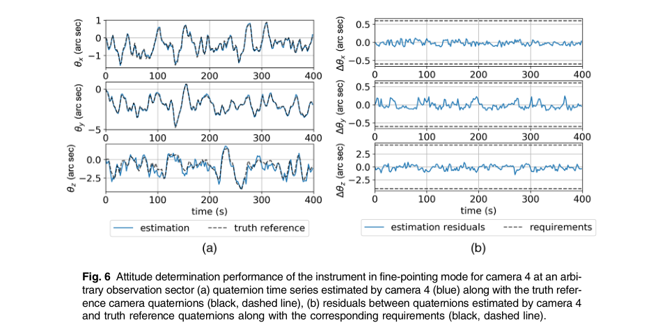
Figure 2. Nguyen et al. Figure 6: Camera 4 estimated and true simulated attitude on the left; their difference on the right. These time series show the distinction between actual pointing motion and the error in measuring it. Ground test/simulation evidence, not flight telemetry. Reproduced excerpt under CC BY 3.0; original DOI.
The paper reports three different quantities that must not be conflated:
| Quantity | Published result | Meaning |
|---|---|---|
| Coarse-to-fine acquisition attitude knowledge | 4.3, 5.2, 5.1, 4.6 arcsec for Cameras 1–4, respectively; $3\sigma$ | Error in estimating the imposed attitude in the spiral test; requirement 20 arcsec |
| Nominal cross-axis attitude knowledge | 0.19–0.42 arcsec; $3\sigma$ across cameras/axes | Camera measurement error; requirement 0.60 arcsec |
| Nominal camera-roll knowledge | 1.41–2.06 arcsec; $3\sigma$ | Camera measurement error around its boresight; requirement 4.20 arcsec |
The numbers above come from Tables 3–4. The paper's summary rounds them to less than 0.4 and 2.0 arcsec, although the detailed table includes 0.42 and 2.06. For numerical work, use the table rather than treating the rounded prose as strict upper bounds. Nguyen et al., pp. 6–7, 12.
The closed-loop simulation then predicts:
| Timescale | Spacecraft X | Spacecraft Y | Spacecraft Z | Requirement |
|---|---|---|---|---|
| 2 seconds | 1.81″ | 2.88″ | 2.80″ | Not listed in Table 5 |
| 1 minute | 0.98″ | 1.60″ | 1.53″ | 2.0″ |
| 30 minutes | 0.011″ | 0.024″ | 0.011″ | Not listed in Table 5 |
| 1 hour | 0.0065″ | 0.021″ | 0.0056″ | 0.06″ |
All entries are the paper's $3\sigma$ forward-integrated-PSD stability metric, after removal of slow velocity-aberration drift, for a particular preflight simulation. They are not instantaneous excursions, a measured operational floor, or universal bounds for all sectors. Nguyen et al., Table 5.
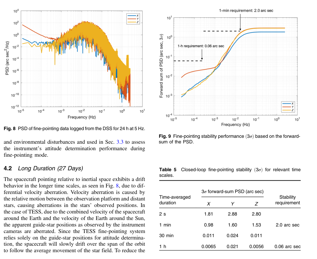
Figure 3. Nguyen et al. Figures 8–9 and Table 5. The low-frequency integrated stability is much smaller than the short-timescale pointing fluctuations. Reproduced excerpt, CC BY 3.0, DOI. The original underlying DSS samples are not distributed with this review; no values have been independently recomputed from raw samples.
Why the hourly number is not an image-blur bound
A long exposure can have an exceptionally stable average centroid while individual photons arrive at a wide range of positions. The source approximates averaging by integrating the PSD only below the reciprocal averaging time. For an actual rectangular temporal average, the exact stationary-process relation instead contains a squared sinc filter:
$$ \operatorname{Var}(\bar a_T)=\int_0^\infty P_a(f) \left[\frac{\sin(\pi fT)}{\pi fT}\right]^2df. $$
Here $a$ is one zero-mean attitude component in arcseconds; $\bar a_T$ is its average over $T$ seconds; $P_a(f)$ is its one-sided power spectral density in arcsec$^2$/Hz; and $f$ is frequency in Hz. This is a general signal-processing clarification, not a claim that TESS flight software evaluates this integral. The forward-PSD cutoff used by the paper is an approximation to such filtering, not an exact boxcar transfer function.
For image analysis, retain both the exposure-mean attitude and its within-exposure variation. The latter can broaden or distort the effective PSF even when the former is almost unchanged.
8. Velocity aberration: the loop follows apparent stars
The first-order aberration used in the thesis can be written
$$ \delta\mathbf u=\mathbf u\times\left(\frac{\mathbf v}{c}\times\mathbf u\right) =\frac{\mathbf v-(\mathbf u\cdot\mathbf v)\mathbf u}{c}. $$
Here $\mathbf u$ is the dimensionless inertial unit direction to a star; $\delta\mathbf u$ is its dimensionless first-order apparent-direction change; $\mathbf v$ is the observer's velocity relative to the inertial stellar frame, expressed in the same coordinates, in units such as km/s; and $c$ is the speed of light in the same velocity units. The thesis uses a Sun-relative spacecraft velocity combining Earth's orbital motion and the spacecraft's Earth orbit. A precision implementation should consistently specify its ephemeris and reference frame. Thesis, equation 4.4.
Because this displacement depends on direction across the sky, it cannot generally be canceled everywhere by a single rigid rotation. Fine guidance drives the best-fit attitude of the selected, valid guide ensemble toward its reference. The spacecraft can therefore drift relative to inertial coordinates while maintaining good guidance residuals, and science stars can retain position-dependent motion relative to their pixels.
The paper describes new guide tables uploaded around perigee for the following orbit, with reference positions chosen to minimize drift near apogee. Its particular 27-day simulation has science-interval drift within approximately ±2 arcseconds. That figure is a scenario result relative to an apogee reference, not the entire physical aberration angle or a guaranteed bound for every target. Nguyen et al., §4.2.
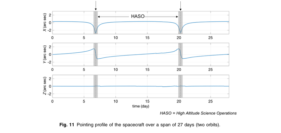
Figure 4. Nguyen et al. Figure 11: simulated spacecraft attitude over two orbits. The three axes respond differently, and perigee intervals are marked. This is the long-timescale behavior removed from the short-timescale stability assessment. Reproduced excerpt, CC BY 3.0, DOI.
Why changing guide cameras shifts the equilibrium
When Earth/Moon stray light makes a camera unsuitable for guidance, its fine-pointing packet is marked invalid and excluded from the control solution. The remaining cameras observe a different subset of the aberrated sky. Their best-fit attitude can differ even if their centroid measurements are individually excellent.
The paper's four-hour Camera 1 dropout test gives small offsets, with geometry-dependent effects; its discussion estimates offsets up to about ±0.2 arcsecond in its worst-case analysis. These are design predictions, not a rule that camera changes are harmless. Later operational notes document significant light-curve consequences of re-enabling a camera. Nguyen et al., §4.3.
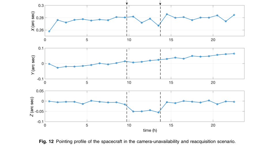
Figure 5. Nguyen et al. Figure 12: attitude before, during, and after Camera 1 is excluded from guidance. A change in guide-camera membership can change the controlled attitude. Reproduced excerpt, CC BY 3.0, DOI.
9. What changed in flight
Early wheel-speed feedback and control tests
The 2018 handbook reports that wheel-speed measurements were noisier than expected at higher wheel speeds. The original controller used those measurements; a modified algorithm omitted them and showed better jitter performance in early testing. This is distinct from saying every pointing disturbance was mechanical wheel vibration. A noisy measurement feeding a controller can itself drive unwanted motion. Instrument Handbook, §8.2.2.
Sector 3's release notes give the operational qualification: the team altered the feedback loop and tuned calibration parameters during designated tests, while its standard science intervals still used the Sectors 1–2 configuration. Thus “tested in Sector 3” must not be rewritten as “used throughout Sector 3.” Test data were flagged for exclusion from normal science processing. Sector 3 DRN4, §1.2.
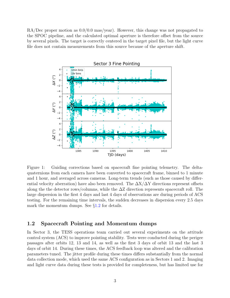
Figure 6. Sector 3 release-note Figure 1 and its surrounding explanation. This is flight-derived guiding telemetry, unlike the preceding preflight figures. The plot averages transformed camera delta quaternions, removes long-term trends, and shows markedly different scatter during control testing and around momentum dumps. It is not an independent absolute-attitude truth sensor. Source: Fausnaugh et al., DRN4 v02, PDF p. 4.
Momentum unloading
Reaction wheels exchange angular momentum with the spacecraft but cannot absorb external torque indefinitely. Thruster firings remove accumulated momentum while wheel speeds are reset. In the early handbook, unloading temporarily returns the spacecraft to coarse pointing, followed by reacquisition and settling. Treat the handbook's durations and early dump intervals as historical operating descriptions; release-note schedules and flags determine the usable intervals for a particular sector.
Sector 12: flight evidence for differential drift
During orbit 31, Camera 1 was unusable for guiding because of scattered Earth light, so Camera 4 alone guided the spacecraft. The release notes report similar pointing stability but larger differential drift in the other cameras, reaching 3 arcseconds, or about 0.14 pixel, in Camera 1. In orbit 32, Cameras 1 and 4 both guided. The notes also explain that re-enabling Camera 1 mid-orbit had previously introduced jumps that triggered false transit detections. Sector 12 DRN17, §1.2.
This establishes an essential distinction: stable guidance on the remaining camera does not guarantee the same image stability everywhere else. The release-note guiding plot below is detrended and therefore does not itself measure the quoted accumulated 3-arcsecond drift; that value is stated in the adjacent operational text. No raw drift measurement has been reconstructed in this review.
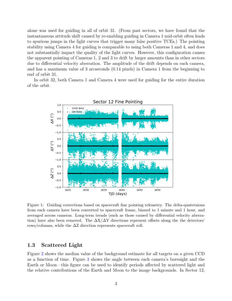
Figure 7. Sector 12 release-note page containing the explanation of single-camera guiding and its differential drift, followed by Figure 1. The plotted telemetry has long-term trends removed; use the text and plot for their different purposes. Source: DRN17 v02, PDF p. 4.
A later check: Sector 104
The downloaded Sector 104 notes report an ACS 5.11 test during the second half of orbit 220, including three wheel-calibration episodes with large pointing dispersions. They explicitly say those calibrations are not required for nominal ACS 5.11 operation. The guide-camera combination also changes by half-orbit, and momentum dumps occur at data-download boundaries. These facts demonstrate continued operational evolution; they do not reveal the new control gains or establish what version runs in every later sector. Sector 104 DRN142, §1 and §1.2.
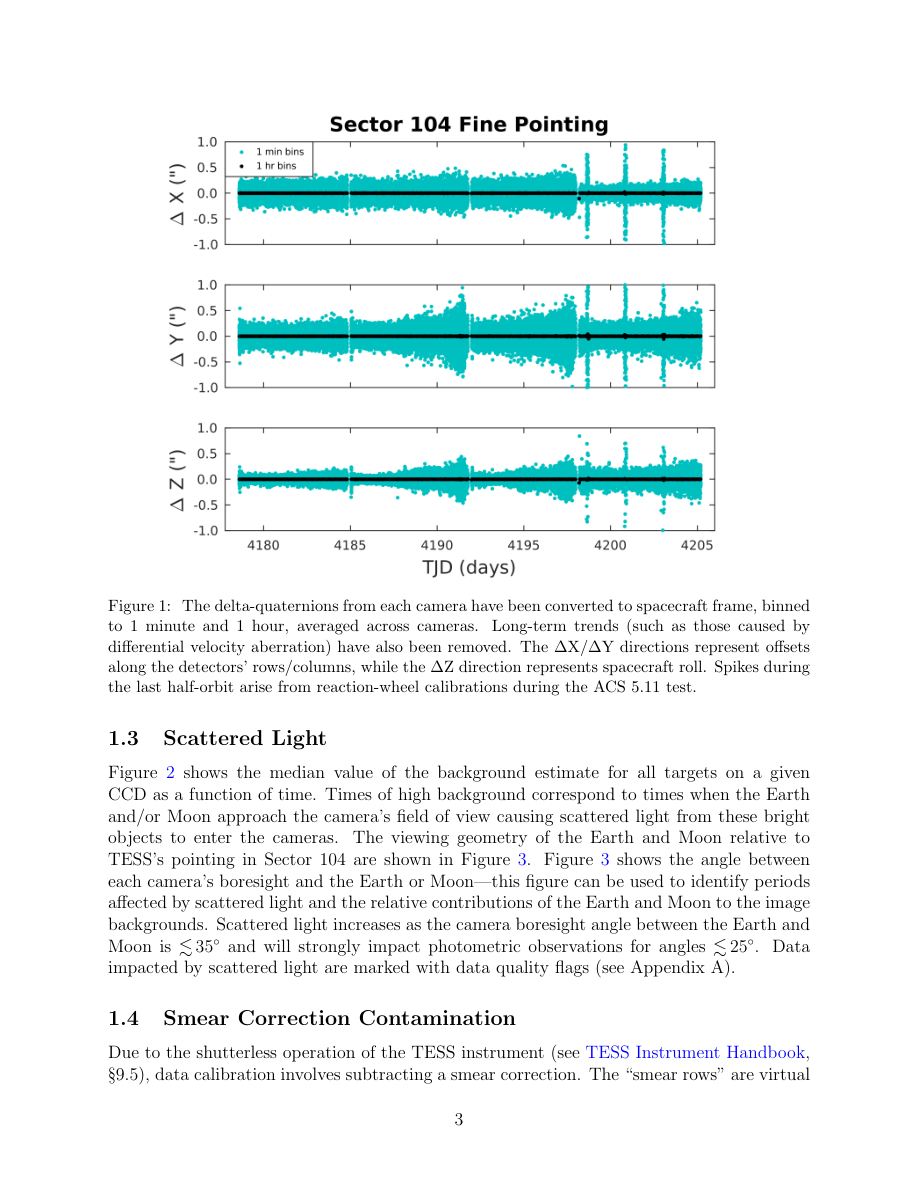
Figure 8. Sector 104 release-note Figure 1. The late spikes are identified by the mission as calibration episodes during the ACS 5.11 test. The plot is transformed, averaged, detrended guide telemetry, not raw individual-star centroids. Source: DRN142 v01, PDF p. 7.
10. Why pointing creates photometric errors
A star's photons are distributed across pixels with unequal response and collected through a finite photometric aperture. Moving the image changes both the aperture losses and the sensitivity weighting. In a blended field, it also changes the neighbor contribution. A useful general description is
$$ F(t)=\sum_{p\in A}g_p\int_{\Omega_p}P\bigl(\mathbf r-\mathbf r_\star(t),t\bigr)\,d^2\mathbf r. $$
Here $F(t)$ is aperture flux in electrons/s; $A$ is the chosen set of aperture pixels; $g_p$ is a dimensionless residual pixel-response factor; $\Omega_p$ is pixel $p$'s area in pixel-coordinate units; $P$ is the stellar image intensity in electrons/s/pixel$^2$; $\mathbf r$ is a detector position in pixels; and $\mathbf r_\star(t)$ is the time-dependent stellar position. This is an interpretive image model, not the onboard control algorithm. Background and neighboring sources would add further terms.
The Nguyen paper simulates this coupling with optical PSFs, stellar and background noise, detector effects, and pointing histories. It finds strong improvement after cotrending against other simulated stars, but this does not prove every observed field reaches that simulated floor or that cotrending preserves arbitrary astrophysical variability. Nguyen et al., §5.
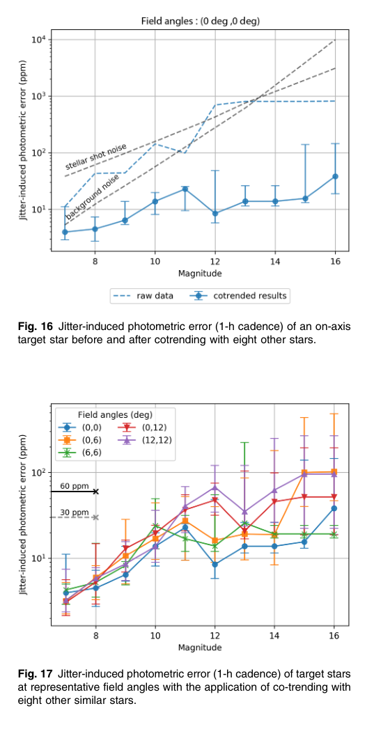
Figure 9. Nguyen et al. Figures 16–17. Top: simulated jitter-induced noise before and after cotrending for an on-axis target. Bottom: cotrended results vary with field position and magnitude. These are model predictions, not measured mission-wide noise floors. Reproduced excerpt, CC BY 3.0, DOI. The underlying simulated image series is not supplied with the article and was not independently reproduced here.
Flight evidence comes from Vanderburg et al.'s HR 858 analysis. Their Figure 2 relates light-curve structure, PSF-width variation, and within-exposure quaternion scatter. They used quaternion-based and other regressors to correct instrumental signatures. This is evidence that sub-exposure jitter affects real photometry, not evidence that their particular detrending recipe is universally optimal. Vanderburg et al. 2019, §2.1.
11. Ground products are not the onboard control variables
Several different objects are often called “pointing”:
| Object | Role | What it does not establish by itself |
|---|---|---|
| Planned sector boresight | Ground observation planning | The actual instantaneous detector location of every source |
| Uploaded guide table | Reference positions for onboard guidance | Perfectly fixed apparent sky geometry throughout an orbit |
| Camera delta quaternion | Small measured attitude error from guide stars | Independent true attitude, free from centroid errors |
| Calibrated FFI WCS | Ground sky-to-pixel mapping | The distribution of motion inside an exposure |
POS_CORR1/2 |
Local column/row motion estimates in science products | A wheel command or a complete PSF model |
| Cotrended flux | Ground estimate with instrumental trends removed | A correction applied to the spacecraft while observing |
The Data Products Description defines POS_CORR1/2 in pixels, including local motion from differential velocity aberration, pointing drift, and thermal effects. It also distinguishes barycentrically corrected science time from spacecraft arrival time through TIMECORR. These distinctions matter when aligning high-rate engineering samples to a science exposure. Data Products Description Rev F, Table 8.
Jenkins et al. describe the ground SPOC processing chain; its calibration, photometry, and systematic corrections run after data downlink. They should not be inserted into the onboard fine-pointing feedback diagram. Jenkins et al. 2016.
12. Implications for SynDiff image modeling
The following are inferences from the documented control architecture, not results of new SynDiff tests.
Separate exposure-mean displacement from within-exposure blur. A local WCS fit measures where a source lands on average. Quaternion scatter or stellar image-shape changes probe the distribution around that mean. A single fitted shift cannot, in general, replace a changing PSF.
Fit the geometry where the science is measured. A global spacecraft rotation maps into different detector motions across the wide field and across cameras. Differential aberration adds a direction-dependent term. An attitude correction evaluated only at one target cannot be assumed to remove the residual field everywhere.
Track guide configuration and operational boundaries. A change from two guiding cameras to one can alter both equilibrium attitude and slow differential drift. Momentum dumps and downlinks can change the pointing state and thermal history. Treat these as possible model boundaries rather than forcing one smooth trend through them.
Expect image-derived pointing to have image-derived biases. Under-sampling, blends, changing background, color-dependent PSFs, and detector response can bias centroids. A quaternion-derived displacement is not automatically an unbiased astrometric truth for every science source. Conversely, the literature alone does not establish a specific chromatic pointing error in a given SynDiff field.
Use the right reference for validation. For a future test, read the sector release notes and masks, align engineering and image time systems, transform quaternions consistently, compare exposure means with local stellar displacement, and compare within-exposure covariance with measured image shapes. Preserve actual data/model/residual stamps when summarizing any correlations. That would test the connection; this review has not measured it.
13. Evidence limits and unresolved implementation details
The sources firmly establish the science-camera feedback architecture, the documented centroid/least-squares method, the timing distinction, and actual operational consequences of camera selection and ACS changes. They do not supply:
- Complete spacecraft flight-control source, gain histories, estimator covariance choices, or a current version-by-version sensor-fusion specification.
- Actual guide-star tables and centroid parameter files for every orbit.
- A full public specification of every flight rejection threshold, background-map update, or invalid-packet handling path.
- Raw synthetic image sequences or proprietary DSS histories underlying all the preflight plots.
- A new empirical characterization of the user's particular science fields.
The figures here are either explicitly labeled explanatory graphics, licensed published simulation figures, or mission-published flight telemetry plots. No numerical curves were fabricated or digitized and presented as newly measured data. Published flight telemetry remains a guide-system measurement; it does not become independent truth simply because it was collected in orbit.
14. Conclusion
TESS fine pointing is a closed loop from science-image centroids to spacecraft reaction wheels. The ground supplies clean guide stars and reference pixel positions; the ADHU estimates per-camera small rotations from those stars; the spacecraft ACS filters the resulting error quaternions and rotates the common spacecraft body. The public literature describes that measurement chain in substantial detail, while the complete spacecraft controller remains only partially disclosed.
The strongest practical conclusion is that fine-pointing status does not imply spatially or temporally invariant science images. Differential aberration, the selected guide-camera ensemble, operational transitions, and sub-exposure jitter all matter. This conclusion is supported both by the design analysis and by flight release notes, particularly Sector 12's single-camera-guidance drift. Confidence is high in the architecture and these mechanisms; numerical performance must be qualified by epoch, frame, averaging metric, and camera configuration. The appropriate next step for SynDiff is a sector-specific comparison of local image motion and PSF shape with exposure-aligned engineering quaternions and guide-camera history—not substituting the preflight stability numbers for measured image behavior.